
Tank transport
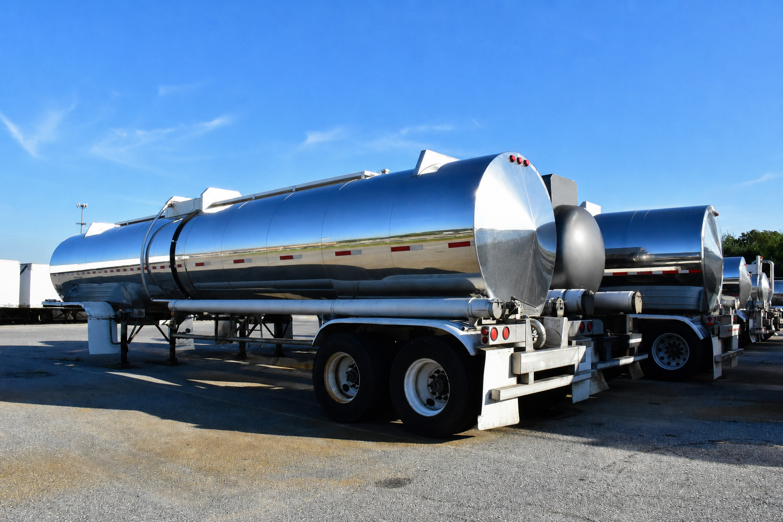
Road tankers, rail tank cars and ISO tank containers, including multi-compartment tanker layouts.
Tank vehicle & tank container cleaning
A configurable system scope for tank-cleaning operations where vessel geometry, residue, throughput, utilities and recovery requirements must work together.
Equipment operation
This video provides a visual reference for the equipment arrangement and operation. The final system configuration is defined against the vessel, cleaning process and site requirements.
Application fit
The initial configuration can be evaluated for a range of transport, process and fixed-vessel cleaning applications.
Road tankers, rail tank cars and ISO tank containers, including multi-compartment tanker layouts.
Dairy tankers, edible-oil tankers and other liquid-handling applications where the operating process requires defined cleaning steps.
Fixed or horizontal storage tanks, reactors, fermenters and small vessel compartments.
IBC applications assessed around access, interior geometry, residue and required process controls.
Application formats
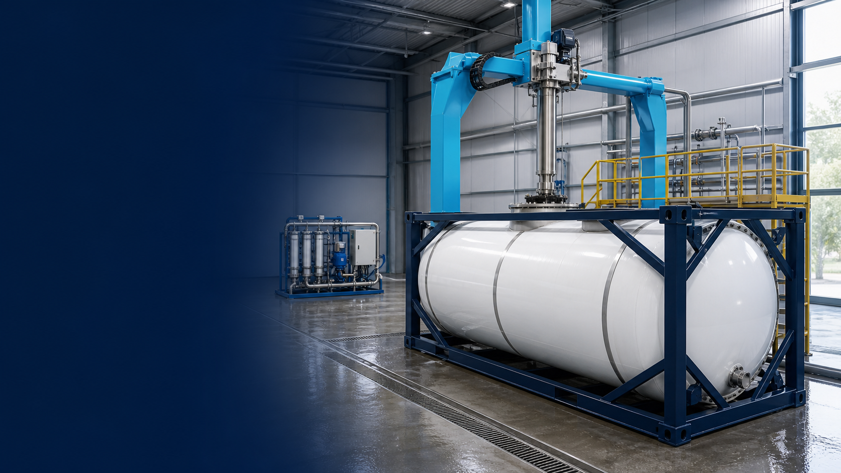
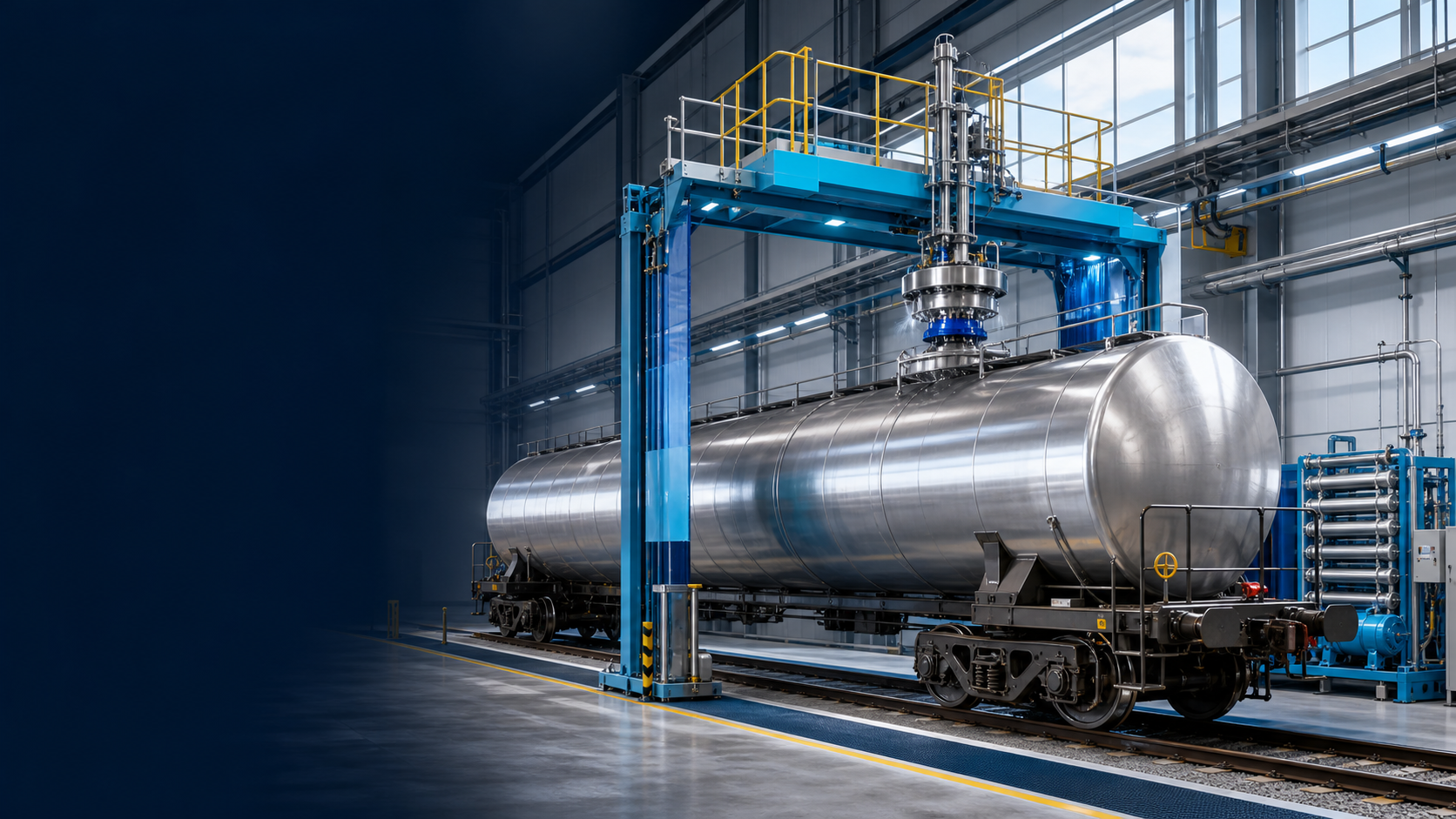
The same process logic is adapted to the tank geometry, access point, operating flow and site interfaces of each application.
Cleaning sequence
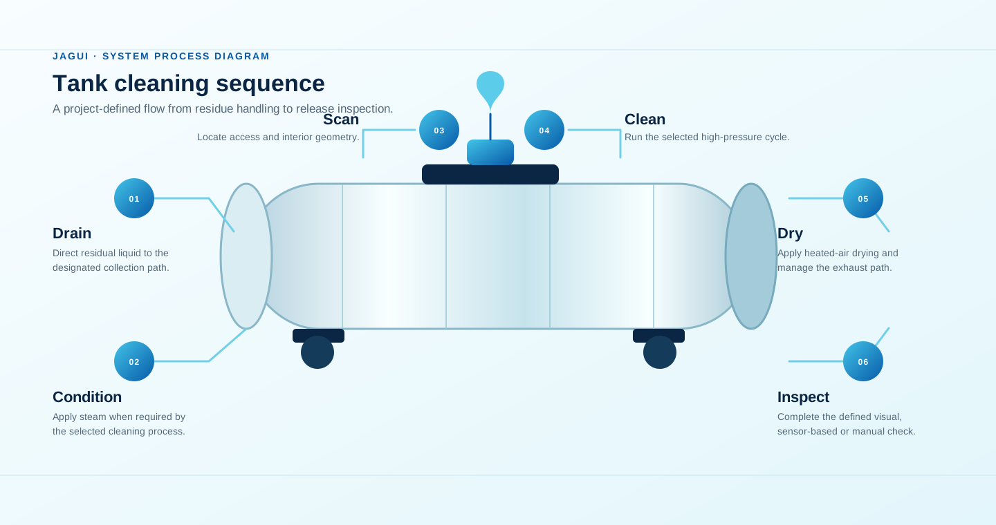
A typical project sequence is adjusted to the vessel, previous cargo or product, local operating procedure and site requirements.
Prepare the vessel and manage residual material before the cleaning cycle.
Apply steam where required to condition or soften remaining material.
Use visual positioning to establish relevant access and interior geometry.
Perform the programmed interior cleaning sequence with collection interfaces.
Apply the selected drying process and connect to the required exhaust treatment path.
Complete the defined inspection process before the vessel returns to service.
Indicative cycle time: approximately 60–80 minutes in one available process reference. Actual timing is confirmed against vessel configuration, residue and operating procedure.
Design reference
These values are configuration references from the supplied project material. They are not a universal specification or a commercial offer.
Reference reach for selected configurations.
Reference range for common tanker layouts.
Selected around the cleaning medium and process.
Reference flow: 60–65 L/min.
Reference: 20,000 m³/h; 3,500 Pa.
Steam-heated process reference.
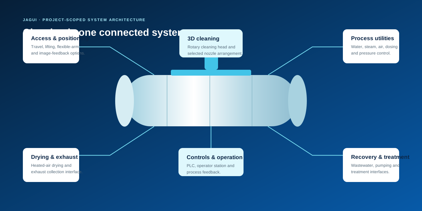
Integrated system scope
The cleaning unit can be paired with process, control, recovery and treatment modules according to the intended site scope.
Cleaning head, lifting and positioning components, flexible-arm arrangement, motion guidance and image feedback.
Steam heat exchange, high-pressure water supply, water softening, detergent dosing and compressed-air equipment.
Steam-heated drying, remote operator station, PLC controls, touch display and integrated operating feedback.
Wastewater collection and treatment interfaces, exhaust collection, washing, filtration and adsorption treatment modules.
Custom steel platform, operating access, lifting support and personnel fall-protection arrangements.
Connections, valves, instrument groups, pumps, pipework and other project-specific installation materials.
Site integration
Initial engineering should review the available water, steam, compressed air, electrical supply, drainage, waste handling, ventilation and installation space. Local voltage, safety and environmental requirements are confirmed for each destination and project.
Reference site input: 0.3–0.4 MPaG supply pressure and at least 200 L/min total flow, subject to final engineering.
Reference site input: 0.5 MPaG working pressure and at least 1,000 kg/h flow, subject to the final heat and safety design.
Reference utilities include 0.7 MPaG compressed and instrument air, plus project-defined local electrical supply.
Wastewater, exhaust and residue-management interfaces are designed around the site process and applicable requirements.
Explore further
JAGUI presents cleaning equipment as part of an operating system, not as an isolated list of components.